
Chris Williams' Journal

Home Page: Chris W
Gosford, NSW, Australia
| Total Posts: 225 | Latest Post: 2026-01-22 |
| Table of Contents | RSS Feed |
Last 2 day have been 'fiddle about' days.
The wiring up and a few decisions to make about what to do about some issues have taken much longer than I had anticipated.
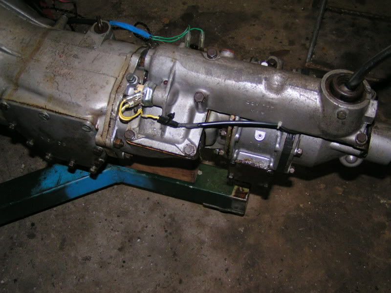
The new harness came with the reverse and OD harness and I'd packed it away a few years ago. Got it out and wired it up. The 3rd, 4th lockout switch had been replaced with a screw terminal version and rather than cut off the clips on the harness I modified some spade terminals and screwed them in and clipped the harness to them.
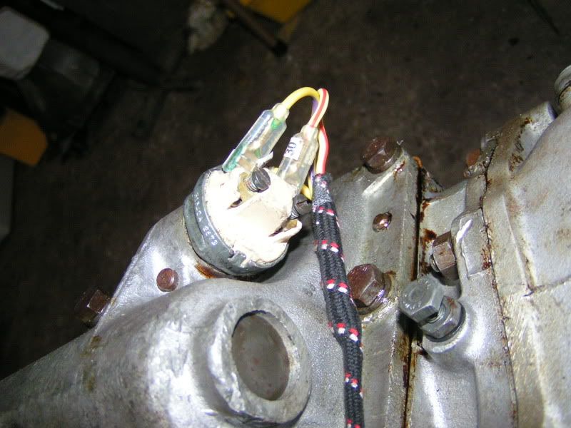
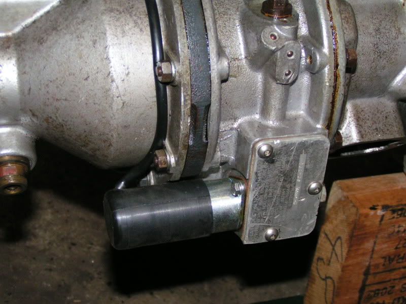
Attached the harness to the side of the gearbox with a combination of cable ties and a 'P' clip. I drilled and tapped an unused spigot in the side of the gearbox. A bit DPO but the result is neat. Also drilled a couple of 3mm holes into casting webs to use cable ties. (Very DPO)
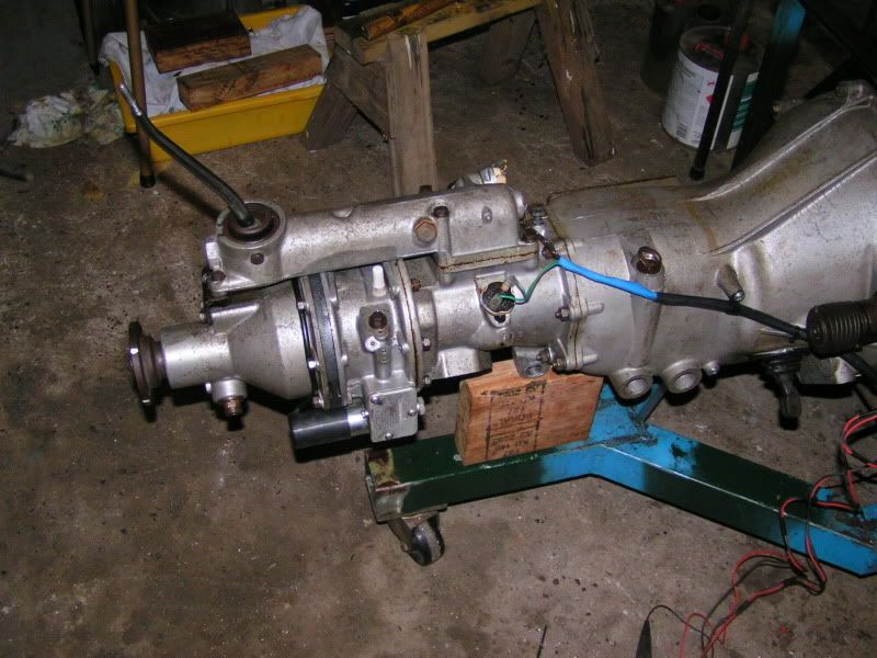
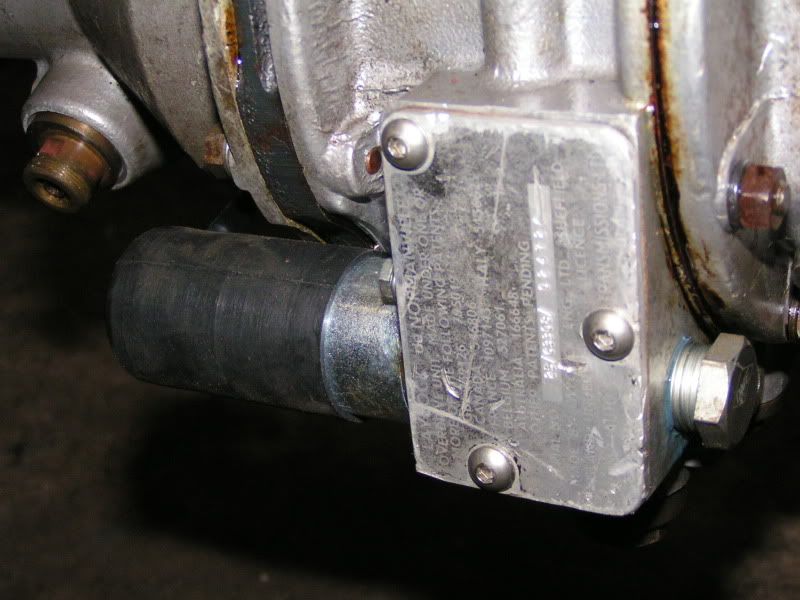
Then it was time to address the adjustment of the OD solenoid. The manual was a bit sketchy in this area but it became clearer when I actually put power to the solenoid. It pulled in a lot further than I thought it would and it was clearer what the manual was describing.
I've covered the control arm up but it is clearly depicted in the manual. A 3/16" hole is in the brass control lever and it matches a hole in the casting behind it. At rest these two should line up. Well the at rest position is debatable and as the plunger can flop around all over the place when no power is flowing I determined close enough was good enough and went about adjusting the arm at the fully engaged position. Logic and the manual and the Moss video mentioned in a previous entry made it clear that the solenoid drew a lot of current when it was being activated but at the end of it's stroke it only needed a small current - less than 2amps to hold it there. A switching mechanism was built into the solenoid at the end of its pull stroke to drop the current from about 15 to 20 amps down to 2amps.
I just had to make sure that the plunger got to this position at the same time as moving the lever to almost it's full movement.
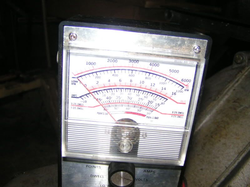
I needed to be able to measure up to 20 amps. Hmm, both my multimeters only go to about 500 Milli amps. I was almost at the point of giving up when I remembered the PO had an ammeter in the dash when I bought the car and started to search for where I'd put that when another light bulb moment and I remembered my old engine analyser that had been given to me maaany years ago but my college mates on my 21st. I sure it had a method of measuring alternator output so it must go into that kind of range. Well I dug it out and found that it did by using a shunt.
Used my jump start battery (almost flat) and hooked it up and got the 2 readings that I required - albeit a bit low because the jump starter was almost flat but there was enough to show a reading of about 10amps and then dropping to about 2amps.
High amp reading: (should be about 20 amps it's not because the battery was almost flat)
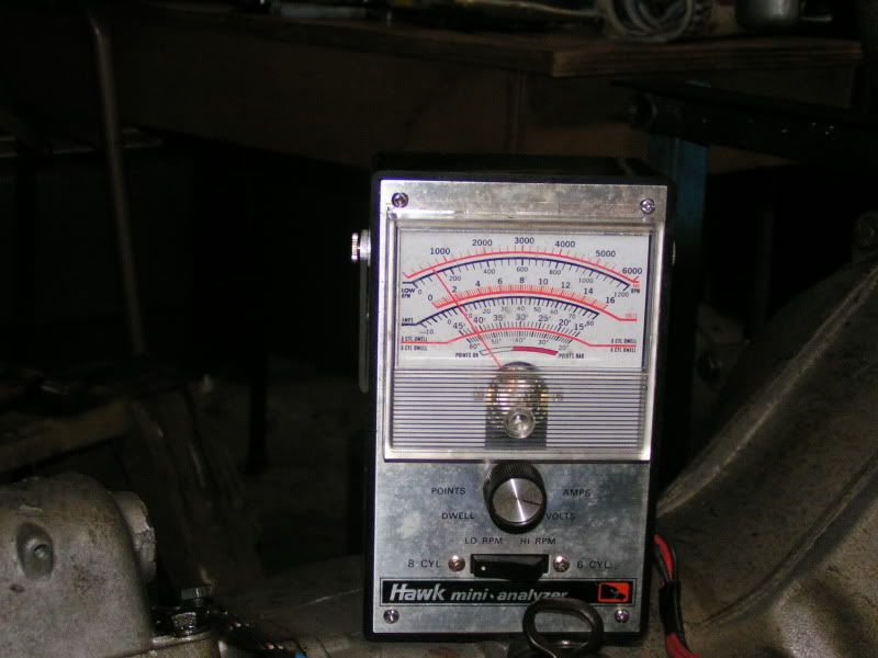
Low amp reading: (Really just a deflection of the needle)
I fiddled about to make sure I was stiil getting full movement on the arm when engaged and it was still a bit slack when disengaged. And I was done.
Used some locktite on the cover plug I got the other day and attached the cover,
All done ready to go!
There was some discussion about the use of the vacuum switch and relay on the forum. I've decided not to use these at this time. I'll just put the link to the discussion by way of explanation.
Link to forum discussion here!
Maybe the lump will go back in tomorrow.
The wiring up and a few decisions to make about what to do about some issues have taken much longer than I had anticipated.
The new harness came with the reverse and OD harness and I'd packed it away a few years ago. Got it out and wired it up. The 3rd, 4th lockout switch had been replaced with a screw terminal version and rather than cut off the clips on the harness I modified some spade terminals and screwed them in and clipped the harness to them.
Attached the harness to the side of the gearbox with a combination of cable ties and a 'P' clip. I drilled and tapped an unused spigot in the side of the gearbox. A bit DPO but the result is neat. Also drilled a couple of 3mm holes into casting webs to use cable ties. (Very DPO)
Then it was time to address the adjustment of the OD solenoid. The manual was a bit sketchy in this area but it became clearer when I actually put power to the solenoid. It pulled in a lot further than I thought it would and it was clearer what the manual was describing.
I've covered the control arm up but it is clearly depicted in the manual. A 3/16" hole is in the brass control lever and it matches a hole in the casting behind it. At rest these two should line up. Well the at rest position is debatable and as the plunger can flop around all over the place when no power is flowing I determined close enough was good enough and went about adjusting the arm at the fully engaged position. Logic and the manual and the Moss video mentioned in a previous entry made it clear that the solenoid drew a lot of current when it was being activated but at the end of it's stroke it only needed a small current - less than 2amps to hold it there. A switching mechanism was built into the solenoid at the end of its pull stroke to drop the current from about 15 to 20 amps down to 2amps.
I just had to make sure that the plunger got to this position at the same time as moving the lever to almost it's full movement.
I needed to be able to measure up to 20 amps. Hmm, both my multimeters only go to about 500 Milli amps. I was almost at the point of giving up when I remembered the PO had an ammeter in the dash when I bought the car and started to search for where I'd put that when another light bulb moment and I remembered my old engine analyser that had been given to me maaany years ago but my college mates on my 21st. I sure it had a method of measuring alternator output so it must go into that kind of range. Well I dug it out and found that it did by using a shunt.
Used my jump start battery (almost flat) and hooked it up and got the 2 readings that I required - albeit a bit low because the jump starter was almost flat but there was enough to show a reading of about 10amps and then dropping to about 2amps.
High amp reading: (should be about 20 amps it's not because the battery was almost flat)
Low amp reading: (Really just a deflection of the needle)
I fiddled about to make sure I was stiil getting full movement on the arm when engaged and it was still a bit slack when disengaged. And I was done.
Used some locktite on the cover plug I got the other day and attached the cover,
All done ready to go!
There was some discussion about the use of the vacuum switch and relay on the forum. I've decided not to use these at this time. I'll just put the link to the discussion by way of explanation.
Link to forum discussion here!
Maybe the lump will go back in tomorrow.

No comments have been posted yet...
Want to leave a comment or ask the owner a question?
Sign in or register a new account — it's free